|
 |
|
|
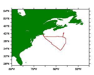
WACS2 Parameter Information
The goal of this cruise was to measure nascent ocean derived aerosols. The Sea Sweep (Bates et al., 2012) was deployed at five stations during the cruise. The Sea Sweep consists of a frame of stainless steel (ss) flatbar 0.61 m wide, 0.91 m long, and 0.91 m high. The upper 0.15 m (bow and stern) and 0.46 m (port and starboard sides) of the frame are covered with ss sheet metal. The top is enclosed with ss sheet metal hood in a cone shape extending 0.3 m above the frame. The Sea Sweep frame is supported by two inflatable pontoon floats (1000 Denier Reinforced) 3 m long attached to aluminum tubing. The frame was adjusted in the pontoons so that the opening at the bow and stern was 1.0 cm above the water under calm conditions.
Three hoses are attached to the Sea Sweep cone top. One hose (1.3 cm ID Pliovic ™ reinforced (braided)) provides compressed air at a flow of 50 L min-1 to two ss diffusion stones (2 um porosity, 2.54 cm diameter, 24 cm long). The diffusion stones are horizontally mounted on the bottom of the Sea Sweep frame 0.75 m below the sea surface. A second hose (5.1 cm ID NutriFLEX Pliovic™) provides a laminar flow air curtain directed downward at the bow and stern ends of the frame. A blower is used to produce a flow of 2 m3 min-1 of particle-free air (charcoal and hepa filtered) to form this curtain. The curtain and side walls prevent ambient air from entering the Sea Sweep. The curtain provides an outward flow of about 1 m3 min-1 (1 m sec-1 face velocity) and an equal dilution flow to the bubbled air in the enclosed space under the hood. The third hose (5.1 cm ID NutriFLEX Pliovic™) brings 1 m3 min-1 of Sea Sweep “sample” air to the PMEL aerosol sampling mast 18 m above the sea surface. This is the same mast and flow rate used during ambient air sampling. The transmission efficiency of the PMEL sampling mast for particles with aerodynamic diameters less than 6.5 m (the largest size tested) is greater than 95% [Bates et al., 2002]. To check for particle losses, simultaneous measurements of the aerosol number size distribution resulting from bubbled seawater were made at the top of the Sea Sweep cone and at the base of the sampling mast with two Aerodynamic Particle Sizers (APS). These measurements showed no measurable loss of particles in either the hose or the mast.
The Sea Sweep was deployed off the port bow of the RV Knorr during WACS2. The ship was positioned with the wind off the starboard bow and steamed slowly (0.2 m sec-1) forward during sampling to ensure a continual renewal of ocean surface water. The forward motion was relative to the current. During some deployments, the ship steamed slowly backwards to keep the water flow under Sea Sweep at 0.2 m sec-1. The ship motion was adjusted visually to keep some bubbles trailing behind Sea Sweep while most of the bubbles were captured in the hood. The ship blocked the true wind. During Sea Sweep sampling the aerosol sampling mast and instruments sampled Sea Sweep so there were no ambient aerosol measurements.
Bates, T.S., P.K. Quinn, A.A. Frossard, L.M. Russell, J. Hakala, T. Petäjä, M. Kulmala, D.S. Covert, C.D. Cappa, S.-M. Li, K.L. Hayden, I. Nuaaman, R. McLaren, P. Massoli, M.R. Canagaratna, T.B. Onasch, D. Sueper, D.R. Worsnop, and W.C. Keene, Measurements of ocean derived aerosol off the coast of California, J. Geophys. Res., 117, D00V15, doi:10.1029.2912JD017588, 2012.
Navigation and Meteorological Measurements
Ship Position (Latitude and Longitude):
In the one minute files the position is treated somewhat differently then all the other data. The position given is the ship's position at the start of the one minute 'averaging' period. All other data are a true average. The PMEL GPS was the primary source, the Ship's GPS was used when there were missing data in the ship's record.
Ship Speed, Course and Gyro:
The ship's GPS speed in knots (Speed Over Ground) and GPS Course in compass degrees (Course Over Ground) are the one minute averages from the GPS (the PMEL GPS as the primary source, the Ship's GPS was the secondary source). To make the one minute averages the 1-second recorded motion vector was separated into east and north components that were averaged into one minute bins. The one minute components were then combined into the ship Velocity Vector. The GyroCompass in compass degrees is the one minute average heading. The primary source was the PMEL GPS compass (Si-TEX Vector Pro), the ship gyro compass data were used when the primary data were missing. The 1-second data were separated into an east and north component before averaging and then recombined. NOTE: The GPS-Course is the direction the ship is moving. The GyroCompass is the direction the ship’s bow is pointing. When the ship is moving at 6 or more knots they generally are the same. Due to water currents, at slow speeds there can be quite a difference between the two. When the ship is stationary, the two are totally unrelated.
Relative Wind:
The primary source for the relative wind data was the PMEL Vaisala WX520 sonic anemometer that was located on the aerosol sampling mast. . For periods of missing data from the PMEL data source the ship’s starboard WX520 sensor at the bow IMET tower was used. The one second relative wind speed and direction data were separated into orthogonal components of "keel" and "beam". These components were averaged into 1 minute averages, and then recombined to relative wind vectors. Wind speed is reported in meters per second and wind direction is in degrees with -90 being wind approaching the ship on the port beam, 0 degrees being wind approaching the ship directly on the bow, and +90 degrees being wind approaching the ship on the starboard beam.
Wind Components/ True Wind Speed/ True Wind Direction:
True wind speed and direction were calculated from the relative wind taking into account the ship’s motion from the GPS and the ship heading from the GPS compass. The true wind vector is given as wind speed in m/s and wind direction in compass degrees. The WindU and WindV are the east and north components of the wind vector (in m/s).
Atmospheric Temperature:
One minute averages in degrees C. The following data sources were used. The PMEL rotronics sensor on the aerosol sampling mast, the PMEL Vaisala WXT520 sensor on the sampling aerosol mast and the two ship owned Vaisala WXT520 sensors on the Ship's IMET bow tower. These 4 sensors generally agreed to better than 0.5 deg C and average of these four sensors was used. There were times when the PMEL data system was down and during those times the average of the Ship's WXT520 sensors was used. Likewise, during times that the Ship's data system was down, the average of the above two PMEL sensors was used.
Relative humidity:
One minute averages in %. The following data sources were used. The PMEL rotronics sensor on the aerosol sampling mast, the PMEL Vaisala WXT520 sensor on the sampling aerosol mast and the two ship owned Vaisala WXT520 sensors on the Ship's IMET bow tower. These 4 sensors generally agreed to better than 5 (RH) % and average of these four sensors was used. There were times when the PMEL data system was down and during those times the average of the Ship's WXT520 sensors was used. Likewise, during times that the Ship's data system was down, the average of the above two PMEL sensors was used.
Barometric Pressure:
One minute averages in units of mb. There were two sources of raw data, the PMEL Vaisala sensor (in the Aerosol van) and the Ship's digital sensor. They both agreed within 0.5 mb. An average of these two signals was used and when only one source was available it is given.
Insolation:
One minute averages in units of watts per square meter. Total solar radiation was measured with an Epply Black and White Pyranometer (horizontal surface receiver -180, model 8-48, serial number 12946) and an Epply precision pyranometer (horizontal surface receiver -180, twin hemispheres, model PSP, serial number 133035F3) that were mounted on the top of AERO van. Both instruments were calibrated by The Epply Laboratory on October 11, 1994. There were times when the sampling mast shaded one or both sensors. There were also times when the ship's mast/bridge shaded the sensors. The shaded data have not been edited out of the 1 minute data record. The data reported here are from the model 8-48, serial number 12946 radiometer and are in watts per square meter and are the average value over the 1 minute sampling period.
Radon:
The PMEL radon instrument is a "dual flow loop, two filtered radon detector". The general features of the instrument are described in Whittlestone and Zahorowski, Baseline radon detectors for shipboard use: Development and deployment in the First Aerosol Characterization Experiment (ACE1), J. Geophys. Res., 103, 16,743-16,751, 1998. The instrument response is due to radon gas, not radon daughters (all of the existing radon daughters are filtered out before entering the decay/counting tank). The instrument registers the total number of decay counts per 30 minute interval on a filter (wire screen) arising from the decay of radon in the tank. The volume of the decay/counting tank was 905 l and the sample flow rate into and out of the tank was typically 70 l/min. The response time of the radon instrument is limited to about 30 minutes by the radiological decay time constants of the radon daughters on the wire screen filter. Thus, the start time given in the data file is 15 minutes prior to midpoint of the counting interval. The instrument was calibrated with a know radon source in Seattle before the instrument was shipped to Boston. Radon concentrations are given in mBq m-3.
Seawater Measurements
Sea Surface Temperature and Salinity:
Sea Surface Temperature (SST) in degrees C and Salinity in PSU were measured with the Ship's Thermosalinograph. The sample seawater was pumped in through an intake that was 5.3 meters below the water line.
Chlorophyll:
Chlorophyll concentrations were measured with a continuous flow Turner model 10-AU fluorometer located in the main lab. The inlet for this system was located 5.3 meters below the water line at the bow of the ship. Discreet filter samples from the ship's seawater system were taken approximately 6 times per day during the cruise. The filters were extracted and analyzed for chlorophyll “a” aboard ship using a second Turner model 10-AU fluorometer operated by Millersville University. The discrete samples were used to calibrate the continuous flow signal. Data are given in mg/m-3.
Seawater DMS:
Seawater entered the ship at the bow, 5.3 m below the ship waterline, and was pumped to the main lab. Every 30 minutes a 5 ml water sample was valved from the water line directly into a Teflon gas stripper. The sample was purged with hydrogen at 80 ml/min for 5 min. DMS and other sulfur gases in the hydrogen purge gas were collected on a Tenax filled trap, held at -5 deg C. During the sample trapping period, 6.2 pmoles of methylethyl sulfide (MES) were valved into the hydrogen stream as an internal standard. At the end of the sampling/purge period the trap was rapidly heated to +120 deg C and the sulfur gases were desorbed from the trap, separated on a DB-1 megabore fused silica column held at 70 deg C, and quantified with a sulfur chemiluminesence detector. Between each water sample the system analyzed either a DMS standard or a system blank. The system was calibrated using gravimetrically calibrated DMS and MES permeation tubes. The precision of the analysis has been shown to be ± 2% based on replicate analysis of a single water sample at 3.6 nM DMS. The automated DMS system is described in greater detail in Bates et al. (J. Geophys. Res., 103, 16369-16383, 1998; Tellus, 52B, 258-272, 2000). The major improvements since these papers are a new automation-data system and a more reliable cold trap consisting of an electrically heated stainless steel tube embedded in an aluminum block that is cooled to -5 deg C with a thermoelectric cooling chip.
Seawater POC, DOC, TOC, TN:
Seawater samples were collected at each station from the seawater line feeding the fluorometer. The samples were acidified with hydrochloric acid (HCl) to a pH less than 2, stored in pre-cleaned glass vials and refrigerated until analysis. Samples were analyzed for total organic carbon (TOC) and total nitrogen (TN) with a Shimadzu TOC-VCSH instrument with a TNM-1 nitrogen unit. A solution of hydrogen potassium phthalate as a carbon standard and potassium nitrate (KNO3) as a nitrogen standard, acidified to a pH of 2, was used to generate five point calibration curves for both TOC and TN with an R2 greater than 0.99. The instrumental method has an uncertainty of ±0.06 ppm for TOC and ±0.02 ppm for TN. The precision for these measurements was less than 2% for both measurements. A 3 ml aliquot of each sample was loaded into the instrument and sparged with zero air to remove any CO2. Finally, 150l was injected into the heated platinum combustion tube. The best three of five injections was averaged to obtain the final TOC and TN concentrations.
Seawater samples were also filtered through quartz fiber filers for particulate organic carbon (POC) analysis. The filters were analyzed for POC using the Sunset Laboratory OC/EC instrument as described below.
Dissolved organic carbon (DOC) was calculated as the difference between TOC and POC.
Aerosol Measurements
Aerosol inlet:
Ambient aerosol particles were sampled at 18 m above sea level through a heated mast. The mast extended 5 m above and forward of the aerosol measurement container. The inlet was a rotating cone-shaped nozzle that was automatically positioned into the relative wind to maintain nominally isokinetic flow and minimize the loss of supermicrometer particles. Air entered the inlet through a 5 cm diameter hole, passed through a 7° expansion cone, and then into the 20 cm inner diameter sampling mast. The flow through the mast was 1 m3 min-1. The transmission efficiency of the inlet for particles with aerodynamic diameters less than 6.5 µm (the largest size tested) is greater than 95% [Bates et al., 2002].
The bottom 1.5 m of the mast were heated to establish a stable reference relative humidity (RH) for the sample air of 51 ± 4%. Twenty one 1.6 cm inner diameter stainless steel tubes extending into the heated portion of the mast were connected to downstream aerosol instrumentation with either conductive silicon tubing or stainless steel tubing for analysis of organic aerosol.
CN and UFCN:
NOTE: Two data files, Sea Sweep and Ambient. See notes on Sea Sweep above.
One of the twenty one 1.6 cm diameter tubes was used to supply ambient air to TSI 3010 (CN_Direct) and TSI 3025A (UFCN_Direct) particle counters. Another one of tubes was used to supply ambient air to a TSI3785 (UFCN_Chem) particle counter. A separate 1/4" line was used to supply air from the top of the mast directly to a TSI 3760 particle counter. The 3760, 3010, 3025 and 3785 measure all particles larger than roughly 12, 12, 3 and 5 nm respectively. The total particle counts from each instrument were recorded each second. The data were filtered to eliminate periods of calibration and instrument malfunction and zero air periods, and periods of obvious ship contamination from the R/V Knorr (based on relative wind and high CN counts). The “best” filtered values were chosen to represent CN>12 (CN) and ultra-fine (UFCN) particle concentrations. The best CN values are primarily from CN_Direct with data from CN_Stack used to fill in periods where the CN_Direct data were not available. Similarly, the UFCN values are primarily from UFCN_Direct with the UFCN_Chem data used to fill in periods where UFCN_Direct data were not available. These "best" data were averaged into one minute periods. One second data are available upon request. The value of -999 was assigned to any one minute period without data.
Chemistry Data, Aerosol Mass Spectrometer (Q-AMS):
NOTE: Two data files, Sea Sweep and Ambient. See notes on Sea Sweep above.
Concentrations of submicrometer NH4+, SO4=, NO3-, POM, and Sea Salt were measured with a Quadrupole Aerosol Mass Spectrometer (Q-AMS) (Aerodyne Research Inc., Billerica, MA, USA) [Jayne et al., 2000; Allan et al., 2003]. The species measured by the AMS are referred to as non-refractory (NR) and are defined as all chemical components that vaporize at the vaporizer temperature (600°C). This includes most organic carbon species and inorganic species such as ammonium nitrate and ammonium sulfate salts but not mineral dust, elemental carbon, or sea salt. However, with the high concentrations of sea salt in the Sea Sweep samples, Na35Cl, Na37Cl, and various halide clusters were detected in the Q-AMS. The ionization efficiency of the AMS was calibrated every few days with dry monodisperse NH4NO3 particles using the procedure described by Jimenez et al. [2003]. The instrument operated on a 5 min cycle with the standard AMS aerodynamic lens. The aerodynamic particle beam forming lens on the front end of the AMS efficiently samples particles with aerodynamic diameters between 60 and 600 nm [Jayne et al., 2000]. For ambient atmospheric samples, this size range generally captures the accumulation mode aerosol and thus is readily comparable to impactor samples of submicrometer aerosol. This is not the case for sea spray particles where the dominant mass mode tails into the submicrometer size range.
Version 0 data have a "Collection Efficiency" (CE) of 1.0 applied to the four “standard” AMS measurements of sulfate, nitrate, ammonium, and organic mass, during ambient aerosol sampling periods. The CE was based on simultaneous collection of filters for ion chromatography as reference standards during ambient aerosol sampling. A CE of 1.0 was used for Sea Sweep sampling periods assuming the POM was fully recovered and the SO4= and Sea Salt concentrations were dependent on the vaporizer temperature. The NH4+ and NO3- data were below the detection limit during Sea Sweep sampling.
The detection limits from individual species were determined by analyzing periods in which ambient filtered air was sampled and are calculated as two times the standard deviation of the reported mass concentration during those periods. The detection limits during WACS2 were 0.04, 0.24, 0.02, and 0.25 ug/m3 for sulfate, ammonium, nitrate, and POM, respectively. Samples below these detection limits are listed as 0 in the ACF file and -8888 in the ICARTT and .itx format file. Missing data are listed as -9999 in the .acf and .ict files and NaN in the .itx file.
Jayne, J.T., D.C. Leard, X. Zhang, P. Davidovits, K.A. Smith, C.E. Kolb, and D.R. Worsnop, Development of an aerosol mass spectrometer for size and composition analysis of submicron particles, Aersol Sci. Technol., 33, 49-70, 2000.
Allan, J.D., J.L. Jimenez, P.I. Williams, M.R. Alfarra, K.N. Bower, J.T. Jayne, H. Coe, and D.R. Worsnop, Quantitative sampling using an Aerodyne aerosol mass spectrometer. Part 1: Techniques of data interpretation and error analysis, J. Geophys. Res., 108(D3), 4090, doi:10.1029/2002JD002358, 2003.
Ion Chemistry Data (Ion Chromatograph):
NOTE: Two data files, Sea Sweep and Ambient. See notes on Sea Sweep above.
Two and seven-stage multi-jet cascade impactors (Berner et al., 1979) sampling air at 50% RH were used to determine the mass size distribution of Cl-, Br-, NO3-, SO4=, methanesulfonate (MSA-), oxalate (Ox-), Na+, NH4+, K+, Mg+2, and Ca+2. Sampling periods ranged from 2 to 13 hours. The RH of the sampled air stream was measured a few inches upstream from the impactor. The 50% aerodynamic cutoff diameters, D50,aero, were 0.18, 0.31, 0.55, 1.1, 2.0, 4.1 and 10 um. Submicrometer refers to particles with Daero < 1.1 um at 50% RH (sum of 4 smallest stages for Sea Sweep samples, 2-stage impactor for ambient samples) and supermicrometer refers to particles with 1.1 um < Daero < 10 um at 60% RH (sum of three larger stages stages for Sea Sweep samples, 2-stage impactor for ambient samples). Aerosol mass size distributions are available for download at: http://saga.pmel.noaa.gov/data/chemdist.php?cruise=WACS2014
The impaction stage at the inlet of the impactor was coated with silicone grease to prevent the bounce of larger particles onto the downstream stages. Tedlar films were used as the collection substrate in the impaction stage and a Millipore Fluoropore filter (1.0-um pore size) was used for the backup filter. Films were cleaned in an ultrasonic bath in 10% H2O2 for 30 min, rinsed in distilled, deionized water, and dried in an NH3- and SO2-free glove box. Filters and films were wetted with 1 mL of spectral grade methanol. An additional 5 mLs of distilled deionized water were added to the solution and the substrates were extracted by sonicating for 30 min. The extracts were analyzed by ion chromatography [Quinn et al., 2000]. All handling of the substrates was done in the glove box. Blank levels were determined by loading an impactor with substrates but not drawing any air through it.
Concentrations are reported as ug/m3 at STP (25C and 1 atm). Values below the detection limit are denoted with a -8888 in the .acf file or zero in the .itx and .ict files, missing data are denoted with a -9999 in the .acf and .ict files and NaN in the .itx file.
Berner et al., Sci. Total Environ., 13, 245 - 261, 1979.
Quinn et al., J. Geophys. Res., 105, 6785 - 6805, 2000.
Organic Carbon (Sunset Laboratory thermal/optical analyzer)
Sub-0.18 m, sub-1.1 m and sub-10 m samples were collected on pre-combusted quartz fiber filters using 2, 2 and 1 stage impactors, respectively, for organic carbon (OC) and elemental carbon (EC) analysis [Bates et al., 2004]. A charcoal diffusion denuder was deployed upstream of the submicrometer and sub-0.18 m impactors to remove gas phase organic species. OC and EC concentrations were determined with a Sunset Laboratory thermal/optical analyzer. Three temperature steps were used to evolve OC under O2-free conditions for quantification. The first step heated the filter to 230C; the second step heated the filter to 600C (AMS vaporizer temperature); and the final step heated the filter to 870C. After cooling the sample down to 550C, a He/O2 mixture was introduced and the sample was heated in four temperature steps to 910C to drive off EC. The transmission of light through the filter was measured to correct the observed EC for any OC that charred during the initial stages of heating. No correction was made for carbonate carbon so OC includes both organic and carbonate carbon. The percentage of carbonate carbon is unknown. EC was below the detection limit for all samples. Super-micrometer OC concentrations were determined by difference between submicrometer and sub-10 m impactor samples without denuders.
Aerosol in-situ Light Scattering and Absorption, Scattering and Absorption angstrom exponents, Single Scatter Albedo, and RH dependence of scattering:
NOTE: Two data files, Sea Sweep and Ambient. See notes on Sea Sweep above.
A suite of instruments was used to measure aerosol light scattering and absorption. Two TSI integrating nephelometers (Model 3563) measured integrated total scattering and hemispheric backscattering at wavelengths of 450, 550, and 700nm (Anderson et al, 1996; Anderson and Ogren, 1998). Sample flow was taken from the AeroPhysics sampling van inlet. One nephelometer (neph_sub10) always measured aerosols of aerodynamic diameter Dae < 10 micrometers; the second nephelometer (neph_sub1) measured only aerosol of aerodynamic diameter Dae < 1 micrometer. Both nephelometers were operated at a sensing volume RH of approximately 60%. The 10 and 1 micrometer cut-offs were made with Berner multi-jet cascade impactors. Two Radiance Research Particle Soot Absorption Photometers were used to measure light absorption by aerosols at 467, 530, and 660nm (Bond et al., 1999; Virkkula et al.,2005) under 'dry' (<25% RH) conditions for sub 10 (psap_sub10) and sub 1 (psap_sub1) micrometer aerosols at the outlet of the respective nephelometers.
On the PMEL Data Sever the ~60% RH, neph_sub10 data are in the TOTSCAT file, the ~60% RH, neph_sub1 data are in the SUBSCAT file. The psap_sub10 and psap_sub1 data are in the PSAP file.
A separate humidity controlled system measured submicrometer light scattering at two different relative humidities, approximately 25% RH and 85% RH (neph_sub1_lo and neph_sub1_hi) with two TSI integrating 3-wavelength nephelometers operated in series downstream of a Berner impactor. The first nephelometer measured scattering of the ~60% conditioned aerosol from the AeroPhysics sampling van inlet at approximately 25% RH after drying of the sample flow using a PermaPure, multiple-tube nafion dryer model PR-94. Downstream of this nephelometer a humidifier was used to add water vapor to the sample flow (6 microporous teflon tubes surrounded by a heatable water-jacket). The sample was conditioned to approximately 85% RH, scattering was measured by the second TSI neph. Humidity was measured by using a chilled mirror dew point hygrometer downstream of the second neph.
On the PMEL Data Sever the neph_sub1_lo data are in the SUBSCATloRH file, the neph_sub1_hi data are in the SUBSCAThiRH file.
DATA COLLECTION AND PROCESSING
Data from both systems were collected and processed at 1 sec resolution but are reported as 60-second averages. Data from each instrument are corrected and adjusted as described below, allowing for derivation of extensive parameters (light scattering and absorption) and intensive parameters (single scatter albedo, Angstrom exponent). Light absorption is box-car averaged by the instrument over a window 10-seconds wide.
For all parameters, the bad value code is "NaN" (-9999 in the .acf fles). Intensive parameters are set to NaN when the extensive properties used in their calculation fell below the measurement noise threshold. Both extensive and intensive properties are set to NaN (-9999) during certain events, such as during filter changes, instrument calibration, obvious instrument failure etc. Negative values of absorption might occur during periods of absorption signals near or in the range of the instrument noise, and are partly shifted into the negative range due to scattering correction.
STP are p_STP=1013.2 hPa, T_STP=273.2 K.
DERIVATION OF MEAN VALUES
EXTENSIVE PARAMETERS
Data from the TSI integrating nephelometers, Neph sub10 and Neph sub1, and f(RH=low) and f(RH=high) are processed as follows:
Span gas (air and CO2) calibrations were made before the field campaign using the standard TSI program. During the campaign zero (particle free air at ambient ater vapor conc.) and CO2 span checks were made at three to four day intervals. The resulting zero offset and span factors were applied to the data.
The TSI nephelometers measure integrated light scattering into 7-170 degrees. To derive total scatter (0-180degrees) and hemispheric backscatter (90-180degrees) angular truncation correction factors were applied as recommended by Anderson and Ogren (1998).
Total and hemispheric backscatter were adjusted to STP. (NOTE: There are no backscattering values available from the f(RH=low) and f(RH=high) nephelometers as discussed above.)
Data from the Radiance Research Particle Soot Absorption Photometers, PSAPs sub1, sub10, and _lo,
are processed as follows:
Reported values of light absorption are corrected for spot size, flow rate, artifact response to scattering, and error in the manufacturer's calibration, all given by Bond et al. (1999). Except the spot size, all corrections were made after data collection, i.e. they are not integrated into the PSAP firmware. However, the PSAP's were flow-calibrated prior to the campaign, and a flow correction was applied based on routine flow checks during the cruise.
Light absorption is adjusted to STP
The f(RH) of scattering data is processed as follows:
Reported values of light scattering at low RH and high RH were corrected to STP.
the exponent describing the f(RH) dependence of scattering was determined using the scattering values of neph_lo_1min (fRH-optics) and neph_hi_1min (fRH-optics) and applying a linear regression of the relationship log(scat_hi/scat_lo) = -gamma*log((1-fracRH_hi)/(1-fracRH_lo)) based on the Kasten & Hanel formula scat_hi=scat_lo(1-fracRH)^(-gamma) [Wang et. al.,2006]
The fRH values given on the data server (SUBFRH) are at the measured high and low RH values. The gamma factor calculated from the equation above is available upon request.
INTENSIVE PARAMETERS
The Ångström exponent for scattering at (450,550,700nm),
A_Blue = -log(Bs/Gs)/log(450/550) A_Green = -log(Bs/Rs)/log(450/700) A_Red = -log(Gs/Rs)/log(550/700)
where Bs, Gs and Rs are light scattering values that apply to 450, 550 and 700 nm, respectively and where these values have been smoothed by averaging over a 30-sec wide window.
The Ångström exponent for absorption at (467,530,660nm),
A_Blue = -log(Ba/Ga)/log(467/530) A_Green = -log(Bs/Rs)/log(467/660) A_Red = -log(Gs/Rs)/log(530/660)
where Ba, Ga and Ra are light absorbtion values that apply to 467, 530 and 660 nm, respectively and where these values have been smoothed by averaging over a 30-sec wide window.
The single scatter albedo of the sub-micron aerosol was calculated as follows:
SSA = Neph1_scat / (Neph1_scat + PSAP1_abs)
where light absorption values and scattering have been averaged over 60 seconds. SSA is given for 532nm, i.e. the nephelometer data was wavelength-shifted to match the PSAP wavelength using the nephelometer based Ångström exponent.
The sub 1 micron and sub 10 micron Scattering Ångström exponents can be found on the PMEL Data Server in the SUBSCATANG and TOTSCATANG files. The sub 1 micron and sub 10 micron Absorption Ångström exponents can be found in the SUBABSANG and TOTABSANG files. The sub 1 micron and sub 10 micron single scatter albedo values can be found in the SUBSSA and TOTSSA files.
REFERENCES
Anderson, T.L., D.S. Covert, S.F. Marshall, M. L. Laucks, R.J. Charlson, A.P. Waggoner, J.A. Ogren, R. Caldow, R. Holm, F. Quant, G. Sem, A. Wiedensohler, N.A. Ahlquist, and T.S. Bates, "Performance characteristics of a high-sensitivity, three-wavelength, total scatter/backscatter nephelometer", J. Atmos. Oceanic Technol., 13, 967-986, 1996.
Anderson, T.L., and J.A. Ogren, "Determining aerosol radiatve properties using the TSI 3563 integrating nephelometer", Aerosol Sci. Technol., 29, 57-69, 1998.
Bond, T.C., T.L. Anderson, and D. Campbell, "Calibration and intercomparison of filter-based measurements of visible light absorption by aerosols", Aerosol Sci. and Tech., 30, 582-600, 1999.
A. Virkkula, N. C. Ahquist, D. S. Covert, P. J. Sheridan, W. P. Arnott, J. A Ogren,"A three-wavelength optical extinction cell for measuring aerosol light extinction and its application to determining absorption coefficient", Aero. Sci. and Tech., 39,52-67, 2005
A. Virkkula, N. C. Ahquist, D. S. Covert, W. P. Arnott, P. J. Sheridan, P. K. Quinn,D. J. Coffman, "Modification, calibration and a field test of an instrument for measuring light absorption by particles", Aero. Sci. and Tech., 39, 68-83, 2005
Wang et. al, Aerosol optical properties over the Northwestern Atlantic Ocean during NEAQS-ITCT 2004, and the influence of particulate matter on aerosol hygroscopicity, submitted to J. Geo. Phys. Res., 2006
CCN Measurements:
NOTE: Two data files, Sea Sweep and Ambient. See notes on Sea Sweep above.
A Droplet Measurement Technologies (DMT) CCN counter was used to determine CCN concentrations at supersaturations, S, of 0.3, 0.4, 0.5, 0.6, and 0.7%. Details concerning the characteristics of the DMT CCN counter can be found in Roberts and Nenes [2005] and Lance et al. [2006]. A multijet cascade impactor [Berner et al., 1979] with a 50% aerodynamic cutoff diameter of 1 µm was upstream of the CCN counter. Each supersaturation level was sampled for 5 min. The first 2 or 3 min (depending on supersaturations involved) of each 5 min period were discarded so that only periods with stable supersaturations are included in the analyzed data set.
The CCN counter was calibrated before and during the experiment as outlined by Lance et al. [2006]. An (NH4)2SO4 aqueous solution was atomized with dry air, passed through a diffusional drier, diluted and then introduced to a Scanning Mobility Particle Sizer (SMPS, TSI). The resulting monodisperse aerosol stream was sampled simultaneously by the CCN counter and a water-based Condensation Particle Counter (WCPC, TSI) in order to determine the average activated fraction (CCN/CN). This procedure was repeated for a range of particle sizes and instrumental supersaturations. Using this procedure, the instrument supersaturation is equal to the critical supersaturation of the particle obtained from the activation curve for an activated fraction of 50%. The critical supersaturation for a given particle size was calculated from Köhler theory (e.g., Fitzgerald and Hoppel, 1984). The supersaturations reported in the text are based on the calibrations and not the instrumental readout which disregards thermal efficiency. The difference between the calibrated values and those reported by the instrument were similar to the difference found by Lance et al. [2006]. The uncertainty associated with the CCN number concentrations is estimated to be less than ± 10% [Roberts and Nenes, 2005]. Uncertainty in the instrumental supersaturation is less than ± 1% for the operating conditions of this experiment [Roberts and Nenes, 2005].
Bates, T.S., D.J. Coffman, D.S. Covert, and P.K. Quinn, Regional marine boundary layer aerosol size distributions in the Indian, Atlantic and Pacific Oceans: A comparison of INDOEX measurements with ACE-1, ACE-2, and Aerosols99, J. Geophys. Res., 107(D19), 10.1029/2001JD001174, 2002.
Berner, A., C. Lurzer, F. Pohl, O. Preining, and P. Wagner, The size distribution of the urban aerosol in Vienna, Sci. Total Environ., 13, 245 – 261, 1979.
Fitzgerald, J.W. and W.A. Hoppel, Equilibrium size of atmospheric aerosol particles as a function of relative humidity: Calculations based on measured aerosol properties, in Hygroscopic Aerosols, edited by L.H. Ruhnke and A. Deepak, pp. 21 – 34, A. Deepak, Hampton, VA, 1984.
Lance, S., J. Medina, J.N. Smith, and A. Nenes, Mapping the operation of the DMT continuous flow CCN counter, Aer. Sci. Tech., 40, 242 – 254, 2006.
Roberts, G.C. and A. Nenes, A continuous-flow streamwise thermal gradient CCN chamber for atmospheric measurements, Aer. Sci. Tech., 39, 206 – 221, 2005.
Aerosol Number Size Distributions:
NOTE: Two data files, Sea Sweep and Ambient. See notes on Sea Sweep above.
One of the 21 1.6 cm diameter tubes was used to supply ambient air to a short differential mobility particle sizer (Aitken-DMPS) and a medium differential mobility particle sizer (Accumulation-DMPS). The two DMPSs were located in a temperature-controlled box at the base of the mast. The temperature was controlled such that the RH of the sample stream was maintained at 60% RH. The Aitken-DMPS was a University of Vienna (Reischle) short column instrument connected to a TSI 3760A particle counter operating with a positive center rod voltage to sample particles with a negative charge. Data were collected in 10 size bins from 20 to 200 nm diameter. The Aitken-DMPS operated with an aerosol flow rate of 1 L/min and a sheath air flow rate of 10 L/min. The Accumulation-DMPS was a University of Vienna (Reischle) medium column connected to a TSI 3760A particle counter operating with a positive center rod voltage to sample particles with a negative charge. Data were collected in 7 size bins from 200 to 800 nm diameter. The Accumulation-DMPS operated with an aerosol flow rate of 0.5 L/min and a sheath air flow rate of 5 L/min. The relative humidity of the sheath air for both DMPS was controlled resulting in a measurement RH in the DMPSs of approximately 60%. Mobility distributions were collected every 5-minutes from a mobility scan that started at even 5 minute intervals and lasted ca. 4.75 minutes.
The mobility distributions from the Aitken-DMPS, Accumulation-DMPS were inverted to a number distribution by assuming a Fuchs-Boltzman charge distribution resulted from the Kr85 charge neutralizer (Stratman, F. and A. Wiedensohler, 1997). The overlapping channels between the two instruments were eliminated in the inversion. The data were corrected for diffusional losses and size dependent counting efficiencies based on pre-ACE-2 intercalibration exercises at IfT. Data are reported in geometric diameter (micrometers) in units of dN/dlogDp (cm-3) at an RH of 60%
The same 1.6 cm diameter tube was used to supply ambient air to the APS (TSI 3321) located in the lower temperature controlled box at the base of the mast. The temperature was controlled to maintain the RH of the aerosol sample stream at 60%.
The APS data reported here are in 34 size bins with the nominal manufacturers aerodynamic diameters ranging from 0.96 to 10.37 µm. Data are reported in aerodynamic diameter (micrometers) in units of dN/dlogDp (cm-3) at an RH of 60%. Additionally, modifications were made to the APS to account for the internal heating of the sample in the APS by its sheath flow and waste heat, which could reduce the measurement RH below 60% RH. First, the sheath flow was conditioned outside the instrument case before reintroduction into the sheath and acceleration nozzle. Second, the inlet tube was insulated to reduce heating at that point. While the temperature at the APS's sensing volume was not measured during sampling, laboratory testing prior to the cruise showed a significant reduction in the internal heating. Before the modifications, the differential temperature between the inlet and the sensing volume was about 3ºC, but after the modifications, the same differential temperature was reduced to less than 1ºC.
All data were filtered to eliminate periods of calibration and instrument malfunction. The value of -999 is assigned to any period without data.
The v0 data are given in four file types: DMPS size distributions where the sizes are geometric diameters, APS size distributions where the sizes are aerodynamic diameters, a combined DMS/APS number size distribution (nsd) where the sizes are in geometric diameter, and a combined DMS/APS mass size distribution (msd) where the sizes are in geometric diameter. The APS data were converted from aerodynamic diameters to geometric diameters using densities calculated from measured chemistry. The combined mass size distribution (msd) was calculated from the number size distribution (nsd) using the same densities. All data were filtered to eliminate periods of calibration and instrument malfunction. The value of -999 is assigned to any period without data. Data are reported in units of dN or dM/dlog(base 10)Dp (cm-3) at an RH of 60%. Format: comma-delimited ASCII. DOY (Julian Decimal Date) (UTC) followed by the dmps, aps size bins as described above. The first two rows of data contain the bin numbers and the midpoint diameters in micrometers of each bin, respectively.
References: Stratman, F. and A. Wiedensohler. A new data inversion algorithm for DMPS measurements. J. Aerosol Sci., 27, 339-340, 1997.
U.S.Dept of Commerce / NOAA / OAR / PMEL / Atmospheric Chemistry